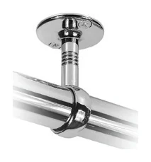
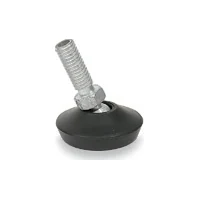
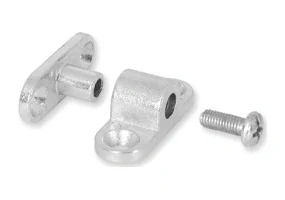
Selection guide
Which dimensions matter for tube connectors and flanges?
Tube-to-surface connections depend on joint direction and screw positions as well as diameter. Evaluate flanges and intermediate connectors for their actual location.
What determines the choice
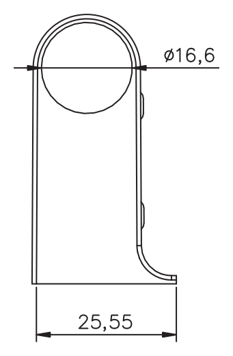
Define the tube profile, fixing surface and joint direction first. A catalogue value such as Ø25 mm identifies the stated diameter; it does not automatically describe the flange's outside size or screw spacing.
For a replacement, compare the tube seat, base shape and fixing holes together. Allow space around the joint for movement and tool access. Confirm the supporting surface and suitable screws separately from the finish of the fitting.
This guide brings together Tube connector 4115 and Tube connector 4116 to help you compare their application and connection details.
Checklist before ordering
- Tube profile and the diameter's location on the drawing
- Base shape and fixing-hole positions
- Joint direction and space for tool access
Compare related models
Follow the product links below for detailed specifications. Confirm any unlisted dimensions before ordering. Matching dimensions alone do not establish connection compatibility.
| Product / reference | Dimension / application | Colour / finish | Pack / carton quantity |
|---|---|---|---|
| Tube connector4115 | Please confirm | Chrome | 96 |
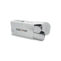 Tube connector4116 | Please confirm | Chrome | 96 |
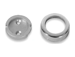 Tube flange4127 | Ø25 mm | Chrome | 100 |
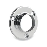 Tube flange4167 | Ø25 mm | Chrome | 100 |
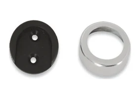 Tube flange (Economy)4128 | Ø25 mm | Chrome | 250 |
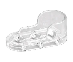 Transparent oval flange2706 | Please confirm | Transparent | 600 |
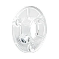 Transparent round flange2705 | Please confirm | Transparent | 600 |
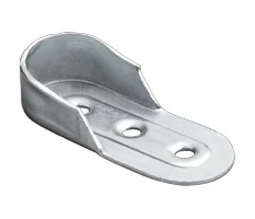 Oval sheet-metal flange2707 | Please confirm | Nickel · Zinc | 1000 |
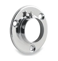 Threaded tube flange4166 | Ø25 mm | Chrome | 100 |
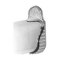 Zamak oval flange4135 | Please confirm | Chrome · Matte chrome | 250 |
Values are taken from the available product information. Pack/carton quantity is not a product load rating.
Read the technical drawings
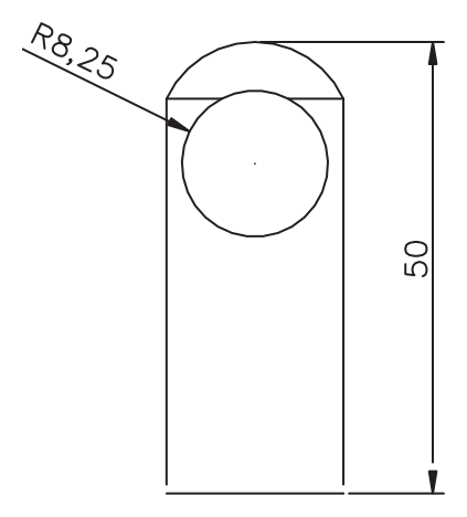
A photograph shows the shape; a technical drawing helps compare connection points and stated dimensions. The drawings below belong to the selected models. Review every image on the product page to confirm the mounting details.
OSENA
Confirm the model for your project
Include the product reference, application dimensions, fixing surface, preferred finish and total quantity in your enquiry. For a replacement part, also share photographs of the existing fixing points so we can clarify the model and supply details together.
Ask for technical details and a quoteSource: OSENA product information and available technical drawings.